You Have 1 Item in your Cart. Price is $199
You Have 1 Item in your Cart. Price is $199
Prestress is typically applied on-site to a variety of structures using post-tensioning of concrete. Members such as slabs and beams are easily post-tensioned on site. Large-span bridge girders are segmentally built using post-tensioning as well.
When a structure is post-tensioned, there is a great deal of flexibility in how the prestress is delivered since the tendon profiles may be easily changed to match the applied loading and the support circumstances. Stage stressing, which involves applying incremental prestress as needed at various building stages as the external stresses progressively rise, is also well suited to post-tensioning.
.png)
.png)
.png)
.png)
.png)
.png)
.png)
The technique of cable-stayed construction has been used and continually developed over the
last 50years.
It is the most common construction choice today when a bridge is required to span more than
300.
Cable-stayed bridges can be either concrete or steel though a combination of both materials
is often chosen.
For concrete cable stayed bridges free cantilever construction is considered economical.
With this method the deck segments can be either precast or cast-in-situ by travelling
shutter arrangement.
In ca cable stayed bridge, depending on its design, the cables carry the bridge deck from
one or both sides of the supporting tower.
The stay cables carry the deck and transfer all bridge loads to the foundations. This is
done by transmitting the cable stay forces,
through its extremeties, at it anchorage points. Stay cables are firmly attached to the
anchorages which are designed to resist the
buckling forces of the loads. Detailing of all anchorages should allow for their safe
construction and accessibility for inspection and
maintenance on completion. In concrete stay-cabled anchorages are placed under the deck.

.png)
.png)


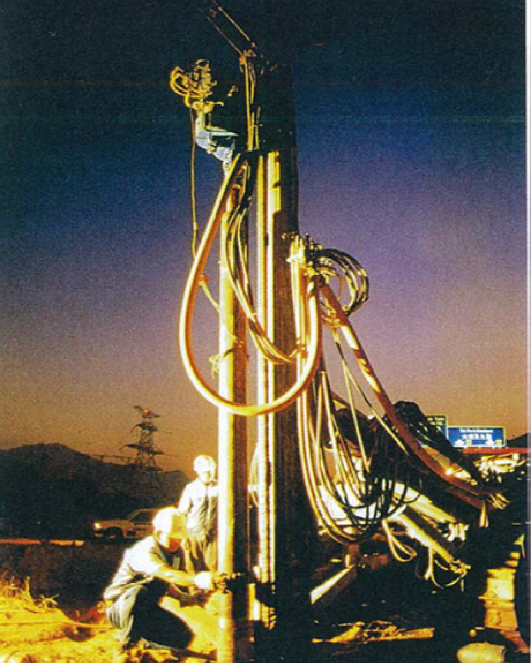
A small-diameter, bored, cast-in-place composite pile, in which the applied load is resisted by steel reinforcement, cement grout and frictional grout/ground bond. Maximum Test Load: The maximum load to which the micropile is subjected during testing
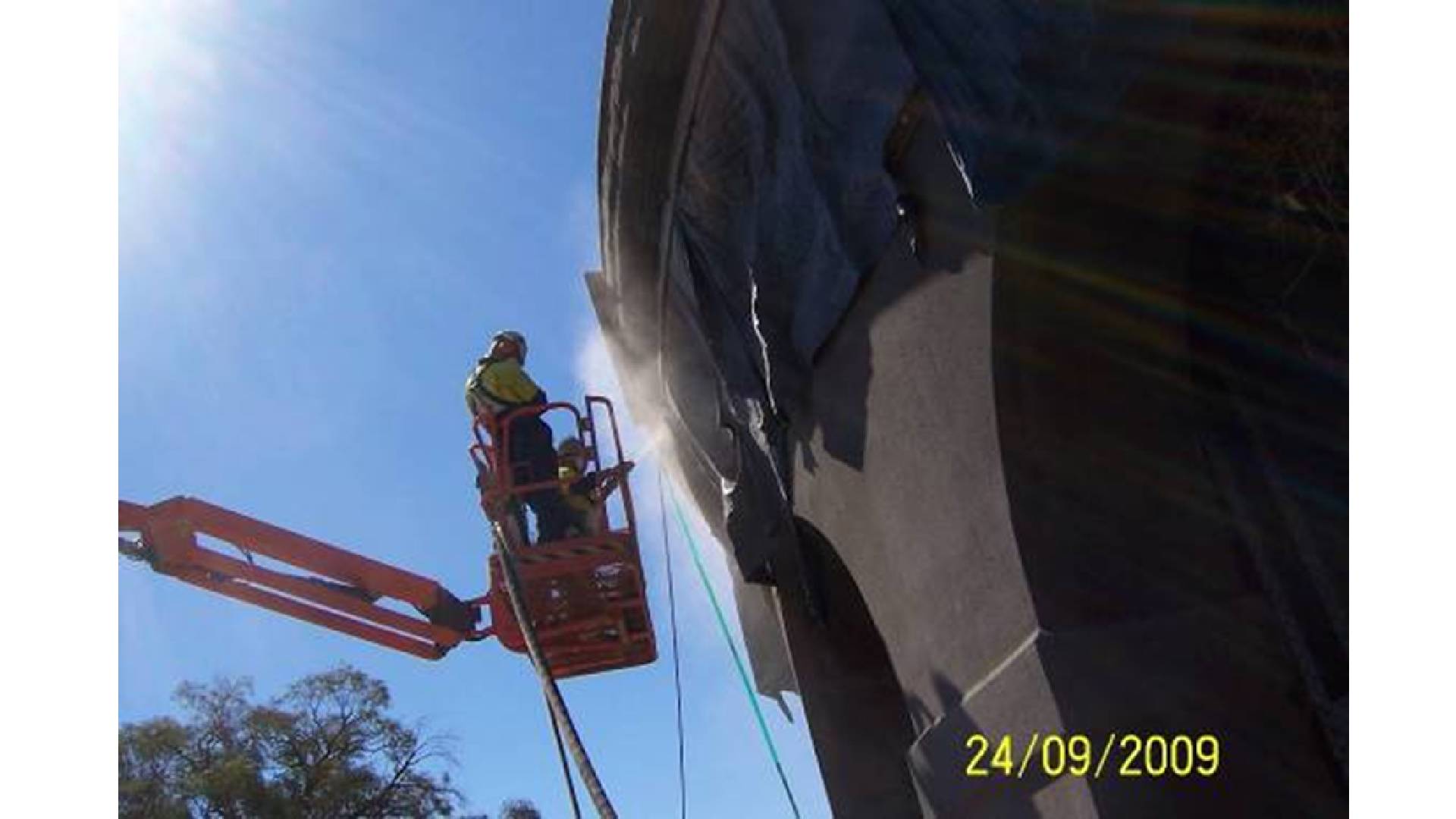
Shotcrete is a mixture of aggregate and portland cement, conveyed by compressed air to the nozzle of a spray gun, where water is added. The wet mixture is then sprayed in place and may be carved or troweled almost immediately
.png)
.png)
.png)
.png)
.png)
.png)
.png)
.png)
.png)
.png)
.png)
.png)
.png)
.png)
.png)
Bridge Launchers - The launching gantry is used to lift and support bridge segments or girders as they are placed while being supported by the bridge piers instead of the ground.
Deconstruction Systems – Bridge demolition includes both full concrete structures removal and partial removal required to modify or rehabilitate an existing structures. Either of these may be performed as phased demolition such as one portion of the structure remains under traffic while the other portion is demolished.
Heavy Lifting - Heavy lifting using the strand jacking technology can be performed to quickly raise or lower almost any load, regardless of the height.
The principle is to progressively build the bridge deck behind one of the abutments.Segments of comparable length are concreted in a formwork or assembled in an assembly area. Then, each segment is match-cast against the previous one and prestressed to the section of the deck already built. As segments are added and slided over special bearings, the increasing length of bridge deck is repeatedly pushed / pulled out of the formwork or assembly area, over the abutment onto the piers, to reach its final position. Provision of a launching nose stressed against the first deck segment will reduce the big bending moments in the deck during launching.
The method consists in building the deck by successive segments, in symmetry on both sides of the pier, by making the built part support the weight of the next segment and of the mobile casting equipment. The deck construction does not have to be linear; it can be sequenced to follow pier construction. This method is ideally suited: to cross high gaps and avoid ground constraints for bridges whose length does not require prefabrication, or with different cross sections or casting lengths
Heavy Lifting - Heavy lifting using the strand jacking technology can be performed to quickly raise or lower almost any load, regardless of the height.
Incremental Launching - The principle is to progressively build the bridge deck behind one of the abutments.Segments of comparable length are concreted in a formwork or assembled in an assembly area. Then, each segment is match-cast against the previous one and prestressed to the section of the deck already built. As segments are added and slided over special bearings, the increasing length of bridge deck is repeatedly pushed / pulled out of the formwork or assembly area, over the abutment onto the piers, to reach its final position. Provision of a launching nose stressed against the first deck segment will reduce the big bending moments in the deck during launching.
Cast-in-place cantilever with form travellers-The method consists in building the deck by successive segments, in symmetry on both sides of the pier, by making the built part support the weight of the next segment and of the mobile casting equipment. The deck construction does not have to be linear; it can be sequenced to follow pier construction. This method is ideally suited: to cross high gaps and avoid ground constraints for bridges whose length does not require prefabrication, or with different cross sections or casting lengths
Copyright © Estructura 2024. All rights reserved.
Created by: IBSS